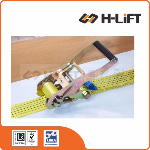
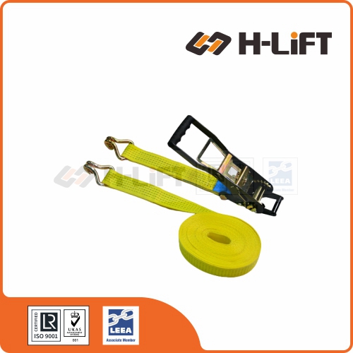
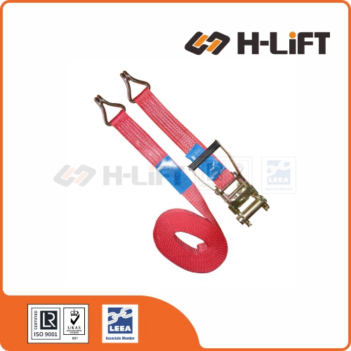
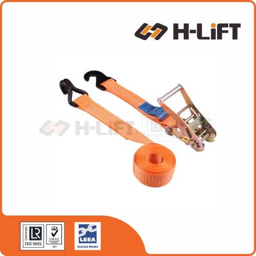
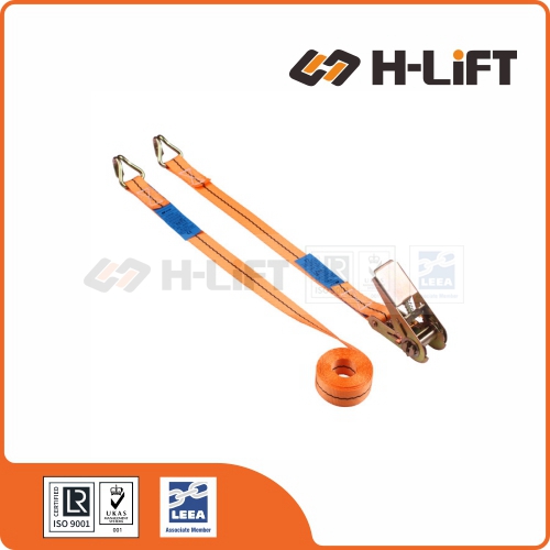
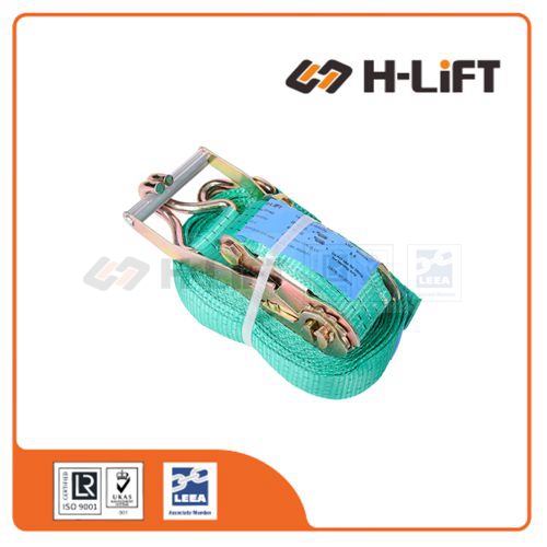
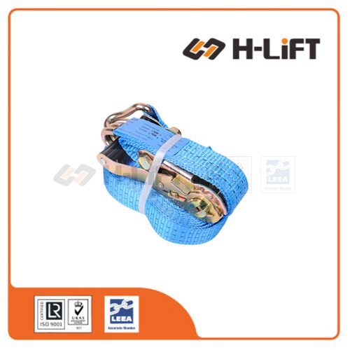
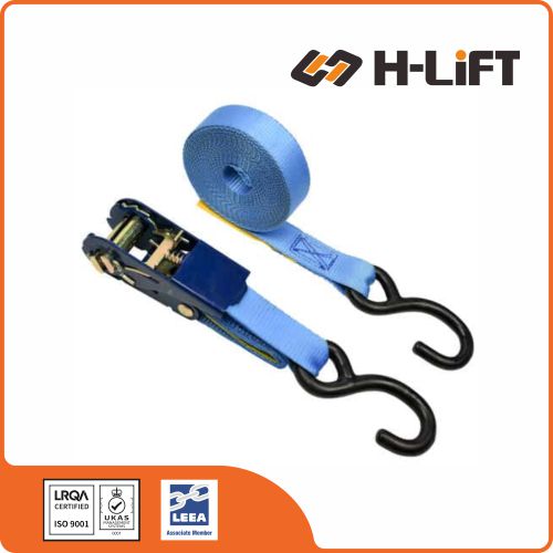
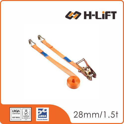
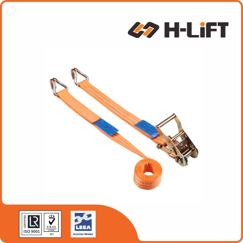
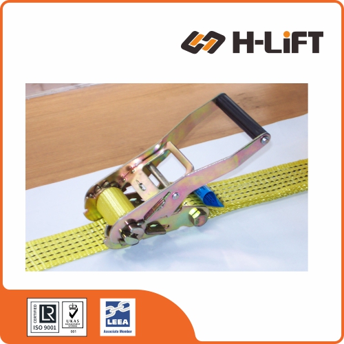
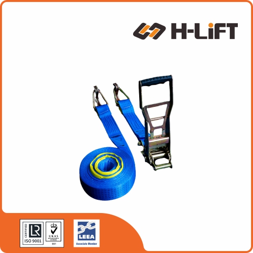
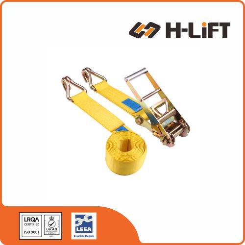
Ratchet tie down straps or lashing straps or ratchet tie downs are fasteners used to hold down cargo or equipment during transport. Ratchet tie down straps are essentially webbing that is outfitted with tie down hardware, made to EN 12195-2.
Ratchet tie down straps (also called lashing straps or tie downs) are fasteners used to hold down cargo or equipment during transport. Tie down straps are essentially webbing that is outfitted with tie down hardware. This hardware allows the tie down strap to attach to the area surrounding the cargo or equipment, loop over the cargo or equipment, and/or attach to the cargo or equipment. It usually also includes a method of tensioning the strap, such as a ratchet.
Two common types of ratchet tie down straps are loop straps and two-piece straps. Loop straps, like their name implies, are a single piece of webbing that is looped around the item to be protected and the two endpoints are brought together at the tie down fastener for fastening and providing tension.Two-piece tie down straps are a single assembly that is constructed out of two separate pieces of webbing each with their own hardware that are fastened at one end to the area surrounding the equipment to be protected and connect to each other, typically at the fastener.
Designed to be attached to the lashing points in order to secure the cargo during transportation, moving, shipping and storage.
Flexible and durable lashings made of high strength polyester strap and steel ratchets, with or without end fittings.
Extremely quick and efficient tie down and release of load.
It is less damaging on contacting cargo surfaces than lashing chains.
Ratchet straps are available in various lashing capacities, lengths and configurations.
Standard: EN 12195-2
Option: Cr6 free galvanized ratchet buckle and end fittings.
Two-piece Web Lashing or Two-piece Strap or Ratchet Strap with Hooks Single Part Web Lashing or Loop Strap or Endless Ratchet Strap
ALWAYS: • Inspect ratchet tie downs before use. • Calculate the lashing force(s) required for the chosen method of load restraint. • Select the capacity and number of ratchet tie downs to provide at least the calculated lashing force(s) • Ensure the lashing points on the vehicle and/or load are of adequate strength. • Position the ratchet tie down so that the load is uniformly spread over its width and protect the ratchet tie down from small radii, especially sharp edges. • Ensure the ratchet tie downs are correctly tensioned. • Exercise care when releasing ratchet tie downs in case the load has become unstable since the lashings were applied.
NEVER: • Use ratchet tie downs to lift a load. • Knot or tie ratchet tie downs. • Overload ratchet tie downs. • Use ratchet tie downs over a sharp edge without edge protection. • Expose ratchet tie downs to direct heat or flames. • Expose ratchet tie downs to chemicals without consulting the supplier. • Use ratchet tie downs which are cut, have loose or damaged stitching, a damaged tensioner or damaged terminal fittings.
Selecting the Correct Ratchet Tie Down The standard for ratchet tie downs is BS EN 12195-2: 2001. Ratchet tie downs are available in a range of capacities and lengths and in various configurations. Some are general purpose. Others are intended for specific applications such as securing cars by their wheels. Selection should start with an assessment of the forces acting on the load. The lashing force(s) required should be calculated in accordance with BS EN 12195-1: 2010. Next check whether the lashing points on the vehicle and/or load are of adequate strength. If necessary apply a greater number of lashings to spread the force across more lashing points. Ratchet tie downs are marked with their lashing capacity (LC). expressed in daN (deca Newton = 10 Newtons) This is a force approximately equivalent to a weight of 1kg.
Using Ratchet Tie Downs Safely Ensure that the tensioner is free to align and not bent over an edge. Ensure that the webbing is not twisted or knotted and that the terminal fittings engage correctly with the lashing points. Ensure that the webbing is loaded evenly across its width and protected from sharp and small radius edges by suitable sleeves or edge protectors
Checking the tension after travelling a short distance is recommended. Ensure that the webbing is protected against sources of friction, abrasion and heat.
In-service Inspection and Storage Ratchet tie downs can easily be damaged by tensioning the webbing across small radius edges or loading the edge of the webbing instead of ensuring the load is spread over its full width. Avoid this by correct placement of the ratchet tie down and the use of protective sleeves and edge protection. However damage may occur accidentally as a result of the load moving in transit hence the need to inspect before each use. Ratchet tie downs may accidentally be exposed to chemicals. Most are manufactured from polyester which is resistant to moderate strength acids but is damaged by alkalis. Weak chemical solutions will become increasingly stronger by evaporation. If appropriate, the webbing may be cleaned with clear water and allowed to dry naturally. Never force dry ratchet tie downs. Ratchet tie downs should be inspected for obvious signs of damage before each use. Do not use the ratchet tie down if any of the following defects are found: illegible markings; damaged, chaffed or cut webbing; damaged or loose stitching; heat damage; burns; chemical damage; solar degradation; damaged or deformed end fittings. Ratchet tie downs will deteriorate gradually over time due to normal wear. We recommends that they should be inspected by a competent person at least every 6 months and a record made of the result.
Ratchet tie downs should only be repaired by someone competent to do so. For long term storage the storage area should be dry, clean, free of any contaminates and shaded from direct sunlight.
General Guidance on Load Restraint
This information is of a general nature only covering the main principles of load restraint.
Terminology
Load restraint is a general term covering all three methods of securing loads to vehicles. Without restraint a load is very likely to slide or topple in transit. The three methods are:
Blocking
Blocking is a securing method where the load lies against fixed structures or fixtures on the vehicle such as headboards, sideboards, stanchions or bracing which prevents the load from sliding or toppling.
Lashing
Lashing is a securing method which uses flexible lashing equipment to tie the load to the vehicle. There are two main types of lashing, frictional lashing (also known as top-over’ lashing) and direct lashing.
Frictional lashing forces the load onto the bed of the vehicle so as to increase the friction between the load and the vehicle bed. See figure 1.
Direct lashing connects a load bearing attachment point on the load to a lashing point on the vehicle. See figure 2.
Many lashing systems are a combination of direct and frictional lashing. Lashing can be used in conjunction with blocking.
Locking
Locking is a securing method where the load is secured to the vehicle by mechanical devices such as the twist locks which secure freight containers.
Figure 1 Example of frictional lashing
Figure 1 illustrates a wooden crate secured by a friction lashing. It is the vertical component of the tension in the lashing which forces the crate onto the bed of the vehicle. The maximum friction is obtained when α = 90º. When α reduces, the friction reduces. For example, when α is 30º, the effect is halved. The amount of friction also depends upon the friction factors of the materials the load and the bed are made from. (See Annex B of BS EN 12195-1 for a table of friction factors.) It can be enhanced by using a friction mat between the load and the bed.
Figure 2 illustrates a dumper truck secured by direct lashing. With direct lashing it is the horizontal component of the tension in the lashing which provides the majority of the longitudinal and transverse restraint. This horizontal component of the tension increases as α decreases.
Whilst the vertical component does increase the friction, the contribution of the friction to the overall restraint is relatively small. In plan view, the longitudinal lashing angle βx controls the balance between the longitudinal and transverse restraint. For a given lashing capacity and vertical lashing angle α, as βx increases, the longitudinal restraint decreases and the transverse restraint increases.
Direct lashing can only be used when both the load and the bed have lashing points compatible with the required strength of the lashing.
Other methods of lashing are loop lashing, spring lashing and round turn lashing. These are often used in conjunction with blocking. The European Best Practice Guidelines illustrates all these methods and explains them in more detail.
Forces acting on the load
Loads on road vehicles are subjected to the forces generated due to the vehicle accelerating, braking and cornering.
EN 12195-1 specifies how the lashing forces should be calculated based on the possible acceleration of the load. The acceleration is expressed as a coefficient which, in effect, is the proportion of the weight of the load which the lashing must restrain in a particular direction.
Figure 3 illustrates the forces which can arise from the acceleration, braking and cornering of an HGV under normal driving conditions. For example, under braking the load can push forward with a force equivalent to 0.8 of the weight of the load.
As well as trying to make the load slide, these forces may try to topple the load. Additional restraint may therefore be required to prevent the load from toppling.
Lighter vehicles generally can accelerate, brake and corner more sharply than those classed as an HGV. Therefore higher forces may act on the load if the gross vehicle weight is less than 3,500kg. Higher forces may also act on the load if the vehicle is transported by rail or sea.
Other considerations
The standards and guidance assume that the bed of the vehicle is equipped with suitable lashing points. Unfortunately this is not always true. It may be possible to achieve adequate restraint by using a greater number of lashings thus sharing the load across more lashing points. However it must be shared equally taking account of possible movement in transit.
Lashing equipment used without protection over the edges of a load can result in the load damaging the lashing equipment. The degree of risk varies with the type of lashing equipment. See the specific guidance overleaf.
Periodically checking the lashing equipment for security and tension during a journey is recommended.
Fixing and releasing load lashings often involves working at height or alongside the vehicle at the roadside, both of which can be hazardous. Users should consider the risks involved and address them when planning the method of load restraint.
Download
We use Cookie to improve your online experience. By continuing browsing this website, we assume you agree our use of Cookie.